Documentation is the love letter you write to your future self - Damian Conway
This is a living document covering prototype hardware that is currently under heavy revision. Whilst there are good reasons for many choices, there are also a few "Friday afternoon" ideas in here. Tread carefully, for here be dragons.
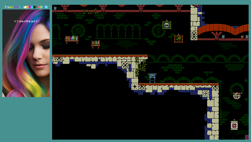
VideoBeast is a graphics chip for 8-bit CPUs that generates high performance arcade quality 2D graphics.
It produces video output at 320x240, 640x480 (4:3) and 424x240, 848x480 (16:9) resolutions in 9 bit (3:3:3) colour. It supports text modes with software defined fonts, tile maps and sprites with 1024 unique graphics and bitmaps in 1, 4 and 8 bit per pixel modes. Up to six layers may be configured using any combination of these graphic types. VideoBeast is implemented in custom hardware and delivers high speed graphics without depending on modern co-processors or software defined video.
It achieves this by providing efficient ways to manipulate large volumes of graphic data. Specifically it provides tiles, sprites and bitmaps that can be composited in up to six layers with transparency, windowing and per-layer scrolling. It also supports effects linked to video signal timing, such as raster effects and sprite and layer multiplexing. VideoBeast features 1MByte of on chip graphics memory, so a large amount of data can be pre-loaded. This reduces the demand on the host CPU. Screen resolutions of up to 848 by 480 (16:9) are supported.
VideoBeast acts as a static RAM chip, occupying 4, 8 or 16KB of host memory depending on hardware configuration with no other interfacing requirements (it can optionally generate a raster-synchronised interrupt signal). In normal operation, the CPU address space (4, 8 or 16K) is mapped to one or more pages of onboard video memory. The top 256 bytes of the address space are mapped to control registers that define page mapping, graphics modes, layer arrangements, palette data etc. The host CPU can read and write to any address in the video memory, and most registers.
The displayed screen is made up of up to six layers (of text, bitmap, tiles or sprites) that are drawn in order. Colours are defined in palettes of up to 256 values, each of which may be one of 512 colours (3:3:3 RGB) or transparent.
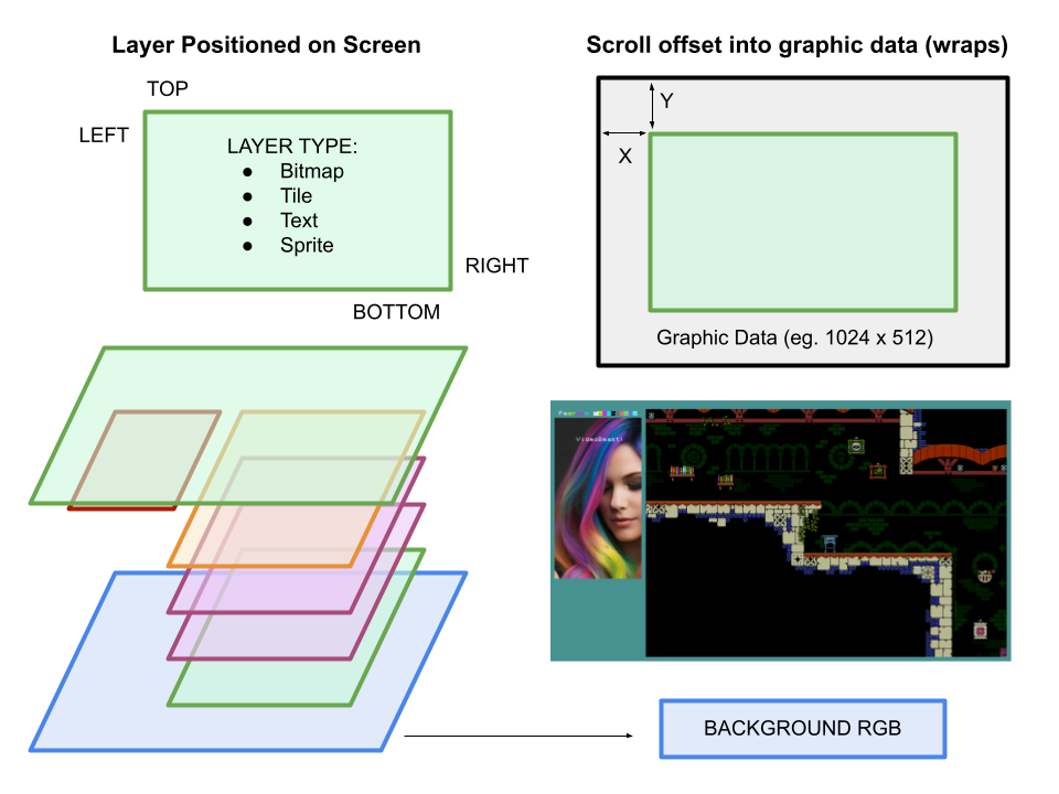
Most layers generate a fixed bitmap size (eg. 1024x512 pixels depending on layer type) regardless of the display mode. This means that software running on the host CPU does not have to take account of different graphics modes for altering the contents of a layer (pixel locations in memory are fixed relative to the base of the layer data). Layers are displayed within a user defined window on screen, with a scroll offset applied (wrapping in X and Y). Layer windows are fixed to 8-pixel boundaries on screen.
Most layers provide reasonable off-screen areas for continuous scrolling, and depending on graphics modes may allow double buffering through switching scroll offset.
From the host CPU perspective, VideoBeast provides a small address space that is suitable for most 8-bit processors to access. However, internally it has 1MB of graphics memory to store text, tiles, sprites and bitmap data. Control registers allow the host CPU to map its smaller address range to any part of the graphics memory. The data in the graphics memory has no fixed arrangement. Instead each layer can specify where its graphics and other data are placed in memory. This allows the host CPU to allocate more or less memory to different graphic types as required by the software being executed. Layers are controlled by registers in layer definition blocks.
In the ideal hardware configuration, VideoBeast presents a 16KB address space to the host CPU (14 address lines, A0-A13). Alternate configurations support smaller 8KB or 4KB address ranges where the host CPU can only dedicate a limited part of its memory map to VideoBeast graphics. If the host system cannot support the full 16KB address space, address lines A13 and A12 may be connected to +5V (high) so that the host system effectively accesses the top 8KB or 4KB of the address space.
In the rest of this document, VideoBeast addresses will be give as though the full 16KB address space is connected to the host system starting at address 0. In this configuration, the host may write or read from addresses 0 to 03FFFh, and VideoBeast will translate (map) addresses in this range to a relevant section of it's internal 1MB graphic memory, or registers.
Regardless of hardware configuration, the host address space is then divided into one or more pages, each of which may be mapped to a different area of VideoBeast's internal 1MB graphic memory. Memory mapping and other configuration is controlled through registers. Registers overlay a variable number of bytes at the top of the address space. By setting appropriate registers, page size can be configured to suit the host hardware arrangement and graphic task, and pages can be mapped to areas of VideoBeast graphic memory to control text, sprites, bitmaps and tiles on screen.
The 16KB address space may be split into 1 16KB page, 2 8KB pages or 4 4KB pages. Each page may be mapped to any 4KB aligned offset in the video memory to write and read from the entire 1Mb address space.
The top 2 bytes (3FFEh and 3FFFh) are always mapped to control registers #FE and #FF which set the display mode, paging and register access. When register access is enabled, the top 256 bytes (3F00h-3FFFh) are mapped to registers. The rest of this document uses the convention that
#XX refers to a register at address 03FXXh.
The fact that registers and mapped pages share the same address space from the hosts perspective leads to a few compromises. It is, however a deliberate choice that maximises the features that can be achieved with a restricted hardware interface. When mapped as a single page, the register overlay means that the top two bytes in the page cannot be read or written to. However, the page mapping may be adjusted within the 1MB range of the graphics memory so that those two bytes are accessible. Page offsets in VideoBeast graphics memory are aligned to 4KB boundaries (or a 2KB boundary in the case of 4KB pages).
All 2 byte or 4 byte values are stored as little endian (LSB first).
Global registers are stored in the 32 byte block #E0-#FF. Bit number X within a byte or word is shown as [X]. Bit sets, from bit X to bit Y are shown as [X:Y]. Any bits that are not explicitly defined should be left as 0.
| Byte | Meaning |
|---|---|
| #FF | [2:0] -> Screen Mode - 0=640x480 1=848x480 2-7=undefined |
| [3] -> Pixel doubling - 0=Off 1=On | |
| [4] -> Testcard - 0=Off 1=On | |
| [7:5] -> Page map - 0=16k 1=8k 2=4k (Low) 3=4K (High), 4=Sinclair | |
| #FE | =243 (0xF3) -> Enable register page. Any other value: Hide and lock all other registers |
| #FD-#FC | Background colour 5:5:5 RGB |
| #FB-#FA | Write->Interrupt on line Read->Current line ([15] Read/Write -> int enabled) |
| #F9 | Bank offset 0 - Page 0 (16K, 8K, 4K) base address / 4KB |
| #F8 | Bank offset 1 - Page 1 (8K, 4K) base address / 4KB |
| #F7 | Bank offset 2 - Page 2 (4K) base address / 4KB |
| #F6 | Bank offset 3 - Page 3 (4K) base address / 2KB |
| #F5 | Lower Registers - |
| [4] -> Register select - 0=Palette 1=Sprites | |
| [3:0] -> Register bank number (64 colours / 16 sprites) | |
| --- | |
| #F4-#F0 | Undefined |
| --- | |
| #EF | SPI Status (Write: 1= start read internal) |
| #EE | SPI target page (4K pages) |
| #ED-#EC | SPI read length (16 bits * 256 byte pages) |
| #EB-#E8 | SPI read address (32 bits) |
| --- | |
| #E7-#E4 | X * Y - Maths accelerator: 32 bit product of the two 16 bit values X and Y |
| #E3-#E2 | Y - 16 bit signed value X |
| #E1-#E0 | X - 16 bit signed value Y |
(Stretch goal) A fast memory fill/copy process might be run when the screen generation is idling. This would allow for rapid updates by removing the need for the host CPU to clear on-screen graphics before drawing additional frames. This might be generalised to a fast horizontal line draw, a triangle fill or a square fill to support vector graphics. Not sure what this would look like in practice.
VideoBeast produces a 9 bit (3:3:3) RGB signal. Since 9 bits are inconvenient to work with, all layers use palettes to translate a 1, 4 or 8 bit pixel value into a 9 bit output. There are (currently, at least) two palettes in VideoBeast, each of 256 colours. One palette is used for bitmap layers, and one palette is used for text, tile and sprite layers.
Where layers have 4bpp (16 colour) graphics, the layer specifies a palette index, which acts as the top 4 bits of the palette value. This allows one of 16 palettes, each of 16 colours to be chosen from the normal 256 colour palette.
Palette values are stored as two bytes, in 5:5:5 RGB format. The top bit indicates a transparent colour. Partial transparency is not supported. This means that a palette takes up 512 bytes. Palettes are accessed through the lower register space (#00 - #7F). 64 colour values are accessible, controlled through the lower register select register #F5. This selects which 64 colour bank within the palettes may be accessed. That 64 colour bank is then available at register locations #00 to #7F.
Layers are composited 'bottom up' over a background colour (registers #FC,#FD). A layer acts as a window into a larger graphic data object such as a bitmap, tilemap or textmap. Whilst the graphic data objects are a fixed size (e.g. a tilemap is always 1024 by 512 pixels), the layer window can be any size on screen, and can display a pixel offset of the graphic data it's connected to (hardware scrolling within the layer window). Multiple layers can point to the same graphic data, or separate objects if required.
Any combination of layer types may be used, however some layers require additional bandwidth from the video memory, so it is possible to exceed the available draw time. 'Expensive' layers include those with 8bpp graphics, sprites and Mode 7. Some testing will be required to determine if a particular layer combination can have problems - but as the firmware stabilises there will be some guidance drawn up as to the limits of the system. If draw time is exceeded, screen corruption may occur.
Layers are composited on the current raster line from the six layer definition blocks. This means that layer multiplexing is possible - the limit is that a maximum of six layers may be used on any given line. Updating the layer definitions as the display is drawn allows larger numbers of layers to be arranged on screen.
(Stretch goal) it may be possible to report "maximum load" for a given frame, so software can measure how hard the graphics system is working and detect potential problems.
Text layers occupy 16K of memory, and display 128 columns by 64 rows of 8x8 pixel characters (1024 x 512 pixels). Each character is stored as two consecutive bytes representing the character index (1 byte), foreground and background colours (1 byte). A palette of 16 colours is selected by the layer definition block, and can include transparent foreground or backround pixels. The layer is drawn with a 1bpp font stored in video memory (256 x 8 bytes, or 2KB).
In addition, text layers can support a one bit per pixel + attribute overlay mode, similar to some early 8-bit computers, allowing high resolution graphics with small memory footprints. To enable this mode, the layer definition block specifies the address of a 64Kb high resolution image. If an image address is set, then any text cell that has a character value of 255 will show the equivalent 8x8 pixel square from the high resolution image, using that cell's attribute values. This allows a high resolution screen of 1025 x 512 pixels with each 8 x 8 pixel square using foreground and background colours chosen from the given 16 colour palette.
Note that whilst the full 1024x512 pixel screen still takes up 64Kb + 16Kb for the attributes, VideoBeast supports special memory mapping modes where a sub-section of this screen area is mapped to more compressed memory layouts. This allows the host to write (for instance) graphics in the Sinclair Spectrum format to memory and VideoBeast automatically decodes the layout to the relevant part of its internal 1024x512 pixel representation.
Tile layers occupy 16K of memory for the tile map, and display 128 columns by 64 rows of tiles. Tiles are 16 colours (4bpp) 8x8 pixels (32 bytes), with the layer therefore being 1024x512 pixels in size. Each tile may use one of 16 palettes. Tile graphics can be defined for up to 1024 unique tiles (occupying 32K). Layers may share tiles, or each layer may use a different tile set as appropriate.
Bitmap layers are either 8bpp or 4bpp (256 or 16 colours from a bitmap palette). Bitmaps take 256K and are either 1024 x 512 pixels (4bpp) or 512 x 512 pixels (8bpp). (Design choice - a 1024x512 8bpp bitmap would be significantly larger than the highest screen resolution, so a large amount of data would be unnecessarily wasted. Limiting 8bpp bitmaps to 512x512 means a full screen 8bpp image in higher resolution modes is possible only by using two bitmaps (with a lot of waste), but a partial screen is more efficient. An alternative would be to define bitmaps in vertical columns of 512 pixels, with the amount of memory used being controlled by number of columns requested for the bitmap.)
Sprite are 16 x 16 pixels, 4bpp (16 colour) chosen from up to 1024 graphics. Sprites are drawn from a sprite list, which is a linked list of 8-byte entries defining the position, orientation, palette and graphic to be drawn. A sprite list may have up to 256 entries. The Sprite layer specifies a entry in the sprite list to be drawn first, then that entry specifies the next sprite to be drawn and so on, until a terminating entry is found. Sprites therefore have a 'depth', with later entries in the list being drawn on top of earlier ones. Using a linked list makes it easy(er) to change the order of sprites without moving large amounts of memory.
Note that sprites are drawn from the specified list on the current raster line. This means that sprite multiplexing is possible - the limitation being a maximum of 256 sprites per line, rather than per entire screen.
(Stretch goal) Mode 7 layers are expensive to draw, so may restrict which other layers are used. A Mode 7 layer is like a 512 x 512 8bpp bitmap layer except that rotation, shear and transformation can be applied (an effect first used in the SNES 'Mode 7'). Raster effects are not possible with a Mode 7 layer, since pixel offsets are persisted across rows on screen.
Layers are defined in 6 x 16 byte blocks from #80 to #DF. Each 16 byte block specifies the layer type, the window on screen that the layer is drawn inside and a scroll offset. Windows are fixed to 8 pixel boundaries. Depending on the layer type, additional parameters are provided in the block, for instance to specify the memory location of the pixel data to be drawn. Layers are drawn in order (bottom to top), starting with the block at address #80.
All layer definitions start with the same 8-byte configuration data.
| Byte | Meaning |
|---|---|
| 0 | [2:0] -> Layer type - 0=Disabled 1=Text 2=Sprite 3=Tile 4=8bpp bitmap 5=4bpp bitmap |
| 1 | Top of window - In units of 8 pixels. Gives 0-2048 |
| 2 | Bottom of window - Inclusive. Gives 7-2055 |
| 3 | Window Left - In units of 8 pixels |
| 4 | Window Right - Inclusive. Gives 7-2055 |
| 5 | [7:0] -> Scroll X[7:0] |
| 6 | [3:0] -> Scroll X[11:8] |
| [7:4] -> Scroll Y[11:8] | |
| 7 | [7:0] -> Scroll Y[7:0] |
The text layer consists of a character map and a font. The text layer is 1024 by 512 pixels, or 128 by 64 characters (occupying 16Kb). The character map has pairs of bytes for each location. The first byte is the character index in the font (255 characters * 8 bytes, or 2Kb). The second is the palette value (0-15) for the foreground (bits 7:4) and background (bits 3:0).
If character = 255, pixel data is taken from a separate 64Kb 1bpp bitmap, using the same attribute value. The bitmap is 1024 * 512 pixels, arranged as 128 bytes for each row (=64Kb total).
| Byte | Meaning |
|---|---|
| 8 | Character map base >> 14 16K page number for character map |
| 9 | Font map base >> 11 2K page number for font (bottom 512K) |
| 10 | [3:0] -> Palette index upper bits |
| [4] -> 0: Normal palette lookup 1: Use Sinclair palette bit layout | |
| 11 | High res bitmap base >> 14 16K page number for 1bpp bitmap (0 disables 1bpp) |
| Byte | Meaning |
|---|---|
| 8 | Bitmap base >> 14 16K page number for bitmap |
| 9 | Unused, leave as 0 |
| 10 | [3:0] -> Palette index |
Memory Usage:
265KB -> 512 x 512 pixel @ 8bpp, or 1024 x 512 pixels @ 4bpp
| Byte | Meaning |
|---|---|
| 8 | Tile map base >> 14 16K page number for tile Map |
| 9 | Tile graphics base >> 15 32K page number for tile graphics |
| 10 |
Memory Usage:
16KB -> 128 x 64 x 2 bytes Tile map (1024x512 or 2048x1024 pixels) 32KB -> 1024 x 32 bytes Tile graphics (8x8 4bpp pixels)
| Byte | Meaning |
|---|---|
| 8 | Sprite graphics base >> 14 16K page number for sprite graphics (1) |
| 9 | First sprite index |
Memory Usage:
128Kb -> 1024 x 128 bytes Sprite graphics (16x16 4bpp pixel tiles)
Notes (1) - Sprite and tile graphics take up to 128K RAM, so for efficiency we might want the base address to be aligned to 128K boundaries.
In addition to the 256 colour and 16 colour bitmap modes, VideoBeast supports a 1bpp (one bit per pixel) mode with a colour attribute map. This is achieved through a text layer configuration where the normal character+attribute text map can allow individual characters to 'peek through' to an underlying high resolution 1bpp bitmap. In this mode, a 64Kb 1bpp bitmap (arranged as 1024x512 pixels, in 128 byte rows) is configured in memory. Then where the text map has a character value of 255, that character is replaced with the underlying bitmap using the specified attribute (foreground and background colour) values.
This layer type allows VideoBeast to support Sinclair style screen layouts with a special page mapping mode. This maps the 16K page visible to the CPU to one of eight areas of a VideoBeast 1bpp bitmap, using the Sinclair memory layout.
| Byte | Meaning |
|---|---|
| #FF | [7:5] = 4 -> Sinclair page mapping mode |
| ... | |
| #F9 | Bank Offset 0 -> Attribute base >> 14 16K page number for character map |
| #F8 | Bank Offset 1 -> Bitmap base >> 14 16K page number for 1bpp bitmap |
| #F7 | Bank offset 2 - Offset 2 -> [2] -> Y8 [1:0] -> X9-X8 Screen offsets |
| #F6 | Bank offset 3 - Offset 4 -> Offscreen base >> 14 16K page number for data outside of screen RAM |
| Bytes | Description |
|---|---|
| 0 | Tile index [7:0] |
| 1 | [7:4] -> Palette index |
| [3] -> 1: Visible. | |
| [2] -> 1: Collide (sprites can hit tile) | |
| [1:0] -> Tile index [9:8] |
Work in progress. In memory sprite lists are expensive to process, so it might be better to move them to on-chip registers. The problem with the register approach is that only one, 256 sprite list can be supported, and changes to the list structure would be 'in-place' (meaning that the list that is being displayed would have to be updated directly rather than loaded on each scan line). This makes raster effects and clean updates somewhat more difficult to organise.
| Bytes | Description |
|---|---|
| 0 | Next sprite index (0 to end chain) |
| 1 | Unused (can be used for double-linked chain) |
| 2 | Sprite pattern index [7:0] |
| 3 | [7:4] -> Palette index |
| [3:2] -> Collision Flags (?) | |
| [1:0] -> Sprite pattern index [9:8] | |
| 4,5 | X position [9:0] (Bit 15 - Mirror) |
| 6,7 | Y position [9:0] (Bit 15 - Flip) |
This is an example memory map, since offsets of graphic data are defined for each layer. However, it illustrates how a number of layers might be laid out to occupy the first 256K of video memory.
| External address | Start | RAM Address | Page | Size | Data | Description |
|---|---|---|---|---|---|---|
| 0000_0000h | 0K | 0000_0000h | 0 | 16K | Text layer 1 | 128 x 64 x 2 bytes (Char+attribute) character map (1024x512 pixels) |
| 0000_4000h | 16K | 0000_2000h | 1 | 16K | Text layer 2 | 128 x 64 x 2 bytes (Char+attribute) character map |
| 0000_8000h | 32K | 0000_4000h | 2 | 2K | Font data 1 | 256 x 8 bitmap |
| 0000_8800h | 34K | 0000_4400h | 2 | 2K | Font data 2 | 256 x 8 bitmap |
| 0000_9000h | 36K | 0000_4800h | 2 | 2K | Font data 3 | 256 x 8 bitmap |
| 0000_9800h | 38K | 0000_4C00h | 2 | 2K | Font data 4 | 256 x 8 bitmap |
| 0000_A000h | 40K | 0000_4600h | 2 | 8K | Undefined | Unused |
| 0000_C000h | 48K | 0000_6000h | 3 | 16K | Tile map 1 | 128 x 64 tiles (1024 x 512 pixels) 2 bytes: tile + attributes |
| 0001_0000h | 64K | 0000_8000h | 4 | 16K | Tile map 2 | 128 x 64 tiles (1024 x 512 pixels) 2 bytes: tile + attributes |
| 0001_4000h | 80K | 0000_a000h | 5-6 | 32K | Tile Data | 1024 x 8x8 pixel 16, colour tiles = 32 bytes/tile |
| 0001_C000h | 112K | 0000_E000h | 7 | 16K | Undefined | Unused |
| 0002_0000h | 128K | 0001_0000h | 8-15 | 128K | Sprite Data | 1024 x 16x16 pixel 16, colour sprite = 128 bytes/sprite |