Legion Emulator
Counter 0 0000
Counter 1 0000
Address reset high 0000
Palette load high 0000
Run count 0000
Pixel queue count 0000
Examples
Display example:Edit Main Memory
Legion GPU Emulator
Version 1.0
Legion is a retro 'fantasy' computer designed to be theoretically implementable in TTL logic, whilst giving performance somewhere between the late 8 bit and early 16 bit computers of the 80's. It comprises a homebrew 16 bit CPU and simple state machine GPU, sharing a common clock and access to 64K x 16 bit RAM.
This is a virtual emulation of the machine's GPU. Details are likely to change and suggestions for improvements are very welcome.
Specs
- Max resolution: 640 x 480
- Native resolution: 320 x 240. 16 colours from 256
- Colour space: 8 bit (3:3:2 R G B) (Image Utils Page)
Rationale
Early 8 bit computers essentially mapped a (more or less) linear block of memory to the display, so the first byte controlled the first pixel(s), the second controlled the next set of pixels and so on. This fixed arrangement meant that any software that wanted to move large amounts of graphics around had to laboriously clear the screen memory and re-draw it from scratch for each successive frame. That placed a hard limit on what was possible in games, even with some clever coding tricks.
Whilst we can imagine a powerful GPU that implements multiple scroll layers, sprites and fast graphic manipulations, the intention behind Legion is to create a machine that can be built from scratch without the use of powerful FPGAs and ultra-fast memory. However, we still want the flexibility to move the screen around and perform some simple palette effects.
Given that most display logic is still basically using counters to read sequences of pixels, Legion takes the step of changing the hard coded memory offsets of early computers into programmable values. The Legion GPU is a state machine that allows the counters and palette data to be controlled by software. This means we can have multiple palettes, scrollable regions and even (limited) changes in resolution driven by a "display program".
State Machine
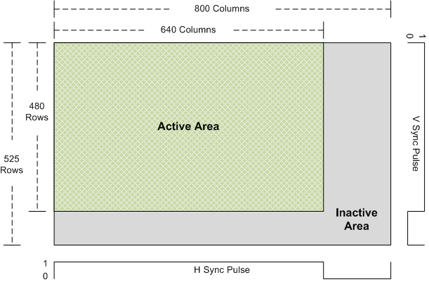
A 640 x 480 VGA display comprises of 800 x 525 'ticks'. The additional ticks outside of the visible 640 x 480 display are horizontal and vertical sync regions, where the display synchronises with the pixel output. The VGA spec typically uses a 25Mhz pixel clock.
The Legion GPU runs on a 3.125MHz clock. On each clock cycle it can fetch a 16 bit value from memory and either execute it as an instruction, or push up to four 4-bit nibbles from it onto the pixel queue. The clock speed means that 100 instructions may be executed on each pixel row of the screen. A GPU clock cycle is therefore equivalent to 8 pixels on a 640 pixel row, or 4 pixels on a 320 pixel row.
During the active area of the display, the pixel queue is popped to give a 4 bit (16 colour) value for each of the 320 pixels on a row. This is combined with an additional 4 bit Palette Select Nibble that can optionally encode the odd/even position of the high resolution pixels. The 8 bit palette address thus formed is used to look up RGB values from a separate Palette RAM. Carefully chosen palette arrangements therefore allow 640x480 by 1 bit, 648x480 by 2 bit, 320x480 by 4 bit and various other graphic layouts.
So long as the pixel queue is not exhausted, the address counters can be updated at arbitrary locations on screen. This allows for hardware scrolling and different screen regions having different resolutions and palette sets. The palette may only be updated during the inactive area of the screen.
Registers
The GPU has five registers.| Register | Bits | Use |
|---|---|---|
| Instruction Address | 16 | Instruction fetch |
| Counter 0 | 18 | Pixel data fetch: 16 bit address, 2 bit nibble offset |
| Counter 1 | 18 | Pixel data fetch, as per Counter 0 |
| Address reset high | 4 | High bits (15:12) for address reset |
| Palette load high | 4 | High bits (7:4) for palette load |
Execution
The GPU is reset on each frame of video output, at the start of line 480, the beginning of the V-Blank inactive region of the display.
On reset, Counter 0, Counter 1, and the Palette Load High registers are set to zero. The high 4 bits of the Instruction Address register are loaded from the Address Reset High register. The remaining 12 bits of the Instruction Address register are set to zero. The pixel queue is emptied. The GPU is placed in Execute mode.
Whilst in Execute mode, the GPU fetches and executes one instruction for each clock cycle.
| Load | |||
|---|---|---|---|
| 00 | 00 aaaaaaaaaann | Load Counter 0: 10 bit (a)ddress low (bits 9:0), 2 bit (n)ibble offset | |
| 01 aaaaaaaaaann | Load Counter 1: 10 bit (a)ddress low (bits 9:0), 2 bit (n)ibble offset | ||
| 10 aaaaaaaaaaaa | Load Instruction Address: 12 bits | ||
| 11 pppprrrgggbb | Load pallet value. 4 bit Low (p)alette address, 8 bit r,g,b | ||
| Load High Registers | 01 | 00 aaaaaaaaaaaa | Counter 0 High: 12 bit (a)ddress high (bits 15:4) |
| 01 aaaaaaaaaaaa | Counter 1 High: 12 bit (a)ddress high (bits 15:4) | ||
| 10 ........aaaa | Address Reset High: 4 bits | ||
| 11 ........pppp | Palette High: 4 bits | ||
| Run | |||
| 11 | c ssss nnnnnnnnn | Start loading from (c)ounter, with Palette (s)elect nibble, total of (n) nibbles | |
The Load instructions load values into the relevant registers. Note that the Load Counter instructions overlap the region of the 18 bit counter that they load - either the lowest 12 bits, or the high 12 bits.
The Load Palette instruction forms an 8 bit palette address from the Palette High register and the 4 bits supplied in the instruction. 8 bits of colour data are stored into the relevant palette entry. Note that Load Palette only works during the inactive screen period (H Blank or V Blank). If called during active display the instruction is ignored.
The Run instruction puts the GPU into Run mode. Whilst in Run mode, the GPU will fetch one 16 bit word from memory on each instruction cycle, using either Counter 0 or Counter 1. The nibbles from the word are then pushed onto the pixel queue, starting at the nibble offset specified in the chosen counter. Thus a maximum of four nibbles will be pushed to the queue on each GPU clock cycle, and the relevant counter incremented appropriately. This is repeated for each GPU clock cycle, fetching a 16 bit word and pushing nibbles to the pixel queue until a total of N nibbles (as specified in the lower 9 bits of the instruction) have been retrieved.
If the pixel queue is full, the instruction blocks until it can continue loading data. Run mode continues until the data transfer is complete, after which the GPU returns to Execute mode and fetches the next instruction. Note that this blocking behaviour synchronises the execution of GPU instructions with the active display area as the pixel queue is filled and emptied.
The Run instruction also sets the Palette Select Nibble, which forms the high four bits of the palette address used to look up on screen pixel colours. Bit 0 of the Palette Select Nibble is ANDed with the lowest bit of the 640 pixel clock. This means that if Bit 0 is clear, the palette address will always have bit 4 as zero. However, if Bit 0 is set, bit 4 of the palette address will reflect the odd or even pixel index of a 640 pixel display. This means that odd pixels will use one palette bank and even pixels will use another. By carefully chosing colours in each bank, the colour of each high resolution pixel can be controlled by one, two or all of the bits in the nibble loaded from memory.
Examples
Given the above, here are some simple examples of GPU programs.
- Default Display
The default display is 320 x 240, with 16 colours. Pixel data starts at address 100.
Address Value Instruction 0x0000 0x7000 Set Palette High to 0 0x0001 0x3000 Palette Colour 0 is black 0x0002 0x31e0 Palette Colour 1 is red 0x0003 0x321c Palette Colour 2 is green 0x0004 0x3303 Palette Colour 3 is blue 0x0005 0x34fc Palette Colour 4 is yellow 0x0006 0x351f Palette Colour 5 is cyan 0x0007 0x36e3 Palette Colour 6 is magenta 0x0008 0x37ff Palette Colour 7 is white 0x0009 0x0400 Counter 0 points to 0x100, nibble offset 0 0x000A 0x1400 Counter 1 points to 0x100, nibble offset 0 0x000B 0xc140 Run with 320 nibbles from counter 0 0x000C 0xe140 Run with 320 nibbles from counter 1 0x000D 0x200b Set instruction address to 0x0B (ie. jump) This program sets up a simple palette of only 8 colours, then points both counters to the same start address, hex 0x100. 320 nibbles (ie. one screen row) are fetched from counter 0, then 320 nibbles (ie. the next screen row) are fetched from counter 1. By starting the counters at the same location, we repeat the same pixel data twice (remember VGA has 480 rows). This gives us 320 x 240 pixels, and takes up 19,200 words.
- Split Display
This creates a split display, with one 256 x 240 region stored in memory from address 0x100, and a column of 64 x 240 pixels stored at address 0x4000 displayed on the right
Address Value Instruction 0x0000 0x7000 Set Palette High to 0 0x0001 0x3000 Palette Colour 0 is black 0x0002 0x31e0 Palette Colour 1 is red 0x0003 0x321c Palette Colour 2 is green 0x0004 0x3303 Palette Colour 3 is blue 0x0005 0x34fc Palette Colour 4 is yellow 0x0006 0x351f Palette Colour 5 is cyan 0x0007 0x36e3 Palette Colour 6 is magenta 0x0008 0x37ff Palette Colour 7 is white 0x0009 0x4010 Counter 0 points to 0x0100 0x000A 0x5400 Counter 1 points to 0x4000 0x000B 0xc100 Run with 256 nibbles from counter 0 0x000C 0xe040 Run with 64 nibbles from counter 1 0x000D 0x4010 Counter 0 points to 0x0100 (repeat previous display line) 0x000E 0x5400 Counter 1 points to 0x4000 0x000F 0xc100 Run with 256 nibbles from counter 0 0x0010 0xe040 Run with 64 nibbles from counter 1 0x0011 0x4014 Counter 0 points to 0x0140 (next row of 256 pixel display) 0x0012 0x5401 Counter 1 points to 0x4010 (next row of 64 pixel display) 0x0013 0xc100 Run with 256 nibbles from counter 0 0x0014 0xe040 Run with 64 nibbles from counter 1 ... repeat for each pair of lines... 0x078C 0x43CC Counter 0 points to 0x3CC0 0x078D 0x54EF Counter 1 points to 0x4EF0 0x078E 0xc100 Run with 256 nibbles from counter 0 0x078F 0xe040 Run with 64 nibbles from counter 1 0x0790 0x2790 Set instruction address to 0x0790 (ie. loop forever) Using the same palette as before, this program switches counters in the middle of the display, having set them up to point to the appropriate pixel row before each line starts. As with the previous program, each line is repeated twice to give us a 240 pixel vertical resolution.