In which we learn about numbers, memory and character mapped graphics
Starting With The Numbers
Before we launch into parts of the game, we need to make sure we understand how computers count. If you’re comfortable with binary, hexadecimal, bytes and words then you can skip this part. However, the way computers think about numbers is fundamental to the way they work, so this is a quick recap of the vital details.
Humans (in most western civilizations at least) count in decimal. We use the digits 0 to 9 to represent 10 unique values, which not uncoincidentally matches the number of fingers on our hands. When we run out of fingers or exceed the capacity of a single digit, we add a second digit to the left - adding a ‘tens’ column.
With two digits, we can count up to 99 (100 unique values), which is the same as 10 to the power of 2 (written as 10^2, or 102, and meaning 10 x 10). Three digits allow us to count up to 999 (103 unique values, or 10 x 10 x 10) and so on. We call this counting base ten.
Computers do not count in base ten.
In fact computers can essentially count up to 1, and that’s it. In their circuits they can have two possible states, ‘off’ (no electricity) or ‘on’ (electricity flowing), like flicking a light switch. We can treat these two states as numbers - ‘off’ means zero, and ‘on’ means one. Two states, 0 and 1. Computers therefore count in base two, or binary.
A single digit on a computer is called a bit (a binary digit). When we want to count past 1, just as in decimal, we add a second digit (a bit) to the left. Instead of being a ‘tens’ column, it’s a ‘twos’ column. With two bits we can count up to 3 (four values):
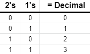
Note that the value of a binary number is just the sum of the column headings where we have a ‘1’. In the table above, ‘11’ in binary is equal to 2+1 = 3 in decimal.
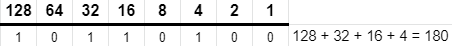
The next column is the next power of two up - so 22 (4). Then 23 (8) and so on. Early computers had very limited numbers of circuits to keep track of these bits, so engineers very quickly settled on using 8 bits together as a convenient unit. With 8 bits we can count up to 255. This is referred to as a byte (from the idea of a large bit?!). The column values for the 8 bits in a byte are:
Unfortunately, converting between binary and decimal is really rather messy. ‘10’ in decimal doesn’t correspond to a convenient round number of bits, so without reaching for a calculator it’s a bit difficult to turn a decimal number into a binary valye in our heads. That’s a problem if you’re interacting with bytes every day. We would like to have a way to count that has a small number of digits when the values get large (like decimal), but that is easier to convert to binary and back again. After a brief dalliance with octal (base 8), engineers chose base 16 (or hexadecimal) as the ideal solution.
Hexadecimal
Hexadecimal (hex to it’s friends) uses sixteen values for each digit rather than the ten values we use in decimal. That conveniently matches the number of values we can represent using 4 bits. In turn, that means that two hex digits exactly match a byte. Because a hex digit falls exactly on a 4 bit boundary, we can convert between the two by just looking at each four bit block (a nibble! really!) and picking the equivalent hex digit.
But.. our normal human way of counting actually only gives us ten digts, so what do we use for the extra six that we need? We could have made up new symbols, or perhaps chosen Greek letters, but the pragmatic engineers instead chose the letters ‘A’ through to ‘F’. So counting in hexadecimal goes ‘0’, ‘1’. . . .’8’, ‘9’ as normal, then ‘A’, ‘B’, ‘C’, ‘D’, ‘E’, ‘F’, ‘10’, ‘11’, ‘12’…
Let’s put that in a table:
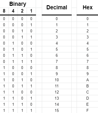
We use hexadecimal a lot when writing software, so it’s worth getting comfortable with it. Note that the letters can be upper or lower case, so F8 is the
same as f8. So that we don’t get confused about which system we’re using to count, we usually mark numbers differently. It’s common to see 0x before a
hexadecimal number or 0b before a binary number in high level languages. In assembly language, which we’ll be using later, another convention is to
mark hexadecimal numbers with a $ (dollar) sign and binary numbers with a % sign. So 0x20 or $20 means twenty hexadecimal, which is 32 in decimal.
Similarly 0b1111 or %1111 is 15 in decimal (or 0xF in hex!).
Bigger Numbers
If computers could only count up to 255, we’d soon run into problems. The solution of course is to keep adding extra columns of digits. But as we have
started with the convention of using 8 bits together as a byte, we’ll add groups of 8-bits to increase the range we can count to. From one byte, we can
use two bytes (16 bits), to count up to 65,535 in decimal (or FFFF in hex). This combination of two bytes is called a ‘word’, and was commonly used
in early computers to locate things in memory. We refer to the two bytes in a word as the ‘high byte’ and ‘low byte’, meaning the larger part of the
value and the smaller. So F800 has a high byte of F8 and a low byte of 00. Notice how hexadecimal makes dealing with these boundaries far easier.
Note that when we’re counting a very large number of bytes, we want to group them. In decimal we group things in thousands, then millions. Binary of course doesn’t exactly map to those same boundaries, but it does come close. 210 is 1024, so we use the term ‘kilobyte’ to mean 1024 bytes. Megabytes are 1024 kilobytes, and so on… So our 16 bit word allows us to address 64 kilobytes (64 x 1024 is 65,536!) of memory.
Things That Aren’t Numbers (Graphics, at last!)
A key thing to understand is that computers really don’t care what those 1’s and 0’s mean. The microprocessor in the heart of your computer largely concerns itself with moving values around, testing them and copying them. We can decide that a value might represent anything depending on what we’re doing with it. One example is that we store text as a series of bytes, where we’ve agreed on a (slightly strange) convention that the number 32 means a space, 65 is a capital ‘A’ and the written digit ‘0’ is actually stored as a a byte with a value of 48 (all decimal numbers). The ASCII character set defines a character or an action for each of the first 127 values a byte may have.
More importantly to us, later on we’ll discover that those numbers can also represent instructions for the computer to execute. When the 6502 microprocessor encounters a byte with a value of 0x69, it will obediently add two numbers together for us. This is the basis of machine code, the heart of all computers.
But right now we want to think about games, and particularly about game graphics. Let’s look at how a computer can use bytes to represent things on screen.
Character Mapped Graphics
Open up the Cerberus emulator in another window by clicking this link
This will start the emulator with a blank screen. In fact the Cerberus display is what we call ‘character mapped’ - it is actually made up of a grid of 40 wide by 30 high cells, each of which can display a character or other symbol. Each cell is a single byte in memory, starting at address $F800.
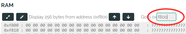
You can see the current contents of that memory, by looking at the RAM section at the bottom of the page. In the Goto box, type in F800 and hit
Enter. The left hand column in the text area below will show the start address of each row, and each row shows 16 bytes of memory as hexadecimal numbers.
At the moment, the screen memory is filled with zeros. As the emulator is configured, character zero is a blank space, so the screen is blank.
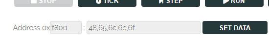
We can manually enter bytes to those addresses and see what happens. In the Address box above the RAM section, type in F800 (we’re going to set
bytes of memory starting at $F800). Then in the data box next to it, type 48,65,6c,6c,6f, then click Set Data to write those five bytes into addresses
$F800, $F801, $F802, $F803 and $F804.
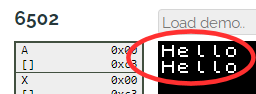
Two things should happen. Firstly, the RAM section below will update to show those five bytes that we’ve written into memory:
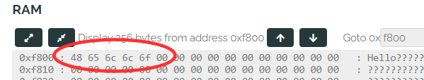
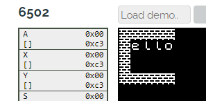
Secondly, on the emulator screen, we should see some text:
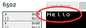
So what has just happened? The first five cells of the display, starting at the top left of the screen and moving left to right, are controlled by the first
five bytes of memory starting at address $F800. Putting $48 into the first byte will display character number 72 (decimal), which happens to be defined
as the set of pixels for the letter ‘H’. In the next byte, the value $65 will display the graphic for the letter ‘e’. The default font (set of graphics) in
Cerberus matches up to the ASCII character set, so we can look up the number for a character, put that number into the byte in display memory and it will
display the relevant character.
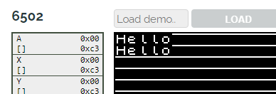
What happens when we get to the end of a row? Remember that Cerberus has a 40 by 30 screen. We can add 40 to our start address, and write the same bytes
to memory to find out. Remebering that 40 decimal is $28 hex, the 40th byte after address $F800 is $F828. Update the address box and hit Set Data again:
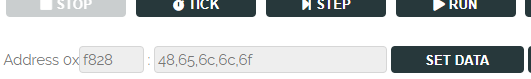
If everything has gone well, we should see this:
In fact, after the first forty bytes define the characters for the first row of the screen, the next forty bytes define the characters for the next row. This
continues all the way down to the end of the screen. As it is 40 by 30 characters, the display occupies 40 x 30 = 1200 bytes in memory. We can calculate the
position of any cell in memory by taking the line number, L (starting at zero at the top) and the column C (zero at the left) and remembering the base
address of the display ($F800) then adding C + (40 x L). To write ‘Hello’ in the middle of the screen this works out as $F800 plus 18 + (40*15),
or $FA6A (it’s up to you whether you do the sum all in decimal, all in hex or a combination - whichever you feel comfortable with.) So, as an exercise, you
can put FA6A in the address box, and press Set Data to check that ‘Hello’ appears where we want it.
Pixel Perfect
Cerberus comes with a font that has all of the standard ASCII characters, plus a few extra ones that help draw borders round screens and so on. However, what happens if we want to display something else other than pure text? The answer lies in where those pixels that make up the characters come from.
Examining the characters closely reveals that they are made up of 8 rows of 8 pixels:
Sound familiar?
Indeed, the characters are defined as bytes of data, each byte providing one row of 8 pixels where a 1 is displayed as white and a 0 as black. Eight
bytes are needed to define a character. Cerberus allows us to change those bytes, so we can define our own graphics - they are stored in memory, just like
the display, but this time from address $F000. The first eight bytes define the pixels for character number 0, the next for character number 1 and so on.
Remember we can display any one of 256 characters (a byte) in each cell, so the character definitions take up 256 x 8 bytes, or 2K of memory. This actually
fits in neatly just before our display area, from address $F000 to $F7FF.
Let’s try it out.
In the emulator as it’s currently set up, you’ll remember most of the display was filled with zeroes. To make things simple, we’ve started Cerberus up
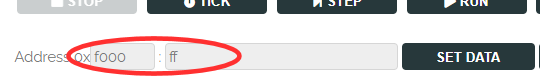
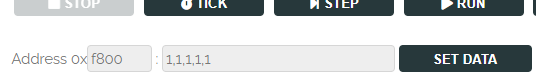
with character number 0 being blank. We can easily change that. Just as we edited memory earlier, let’s write some data to the character area. Put the
value F000 in the address box (the first byte of character number 0). In the data box, just put in a single value of FF (all ones). Click Set Data
and what happens?
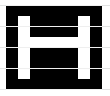
We’ve set all of the pixels in the first row of character number 0 to ‘1’, or white - so we get a screen of stripes!
You can put it back to normal by changing the FF back to 0 and hitting Set Data again if you want. Note that you can also do all of this with a
physical Cerberus board, with the command line providing commands that allow you to write data to memory and display bytes just as we do in the emulator.
Building Walls
Now that we know how the display is arranged, and how we can change the pixels of the characters it displays, we can think about how our game will draw levels. Just like Cerberus, the 8-bit computers that Manic Miner was written for used very similar display arrangements, with bytes providing rows of 8 pixels at a time, and characters occupying 8 by 8 pixel blocks. Levels are made up of ‘wall’ characters, ‘floor’ characters and so on, that fit together neatly.
To illustrate this, let’s try creating a wall character and putting it on screen. Here are the pixels that will make it up, with the binary and hex values displayed:
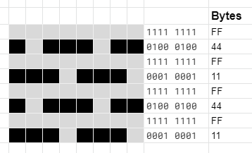
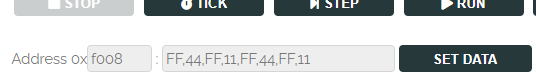
Let’s write those 8 bytes into the locations for character number 1. That will be at address F008 in character memory ($F000 plus 8 * 1)
Now we’ve defined our wall character, we can put it on screen by setting the relevant character in the display memory to 1, the same we we wrote ‘Hello’ before:
By working out the right address for each character on screen, we can draw some walls wherever we want:
Saving It
We can work out the character definitions for all of the things we see on screen this way, and then draw our levels by manually entering in the
relevant bytes at the right address. Many early games were designed in exactly this manner, with squared paper and hand written tables for the right
addresses of locations on screen. Having designed a screen we like we can also save out both the character definitions and display map. Remember that
the character definitions start at address F000 and are then immediately followed by the 1200 bytes of the display map. This makes up a total of 3248
bytes. In the emulator, we can save those bytes to disk and load them whenever we want.
To do so, set the address box to F000 and the byte count in the Save button to 3248:

Click the Save Bytes button, and your browser will download a file that contains all of the data displayed on screen. You can load this back
in again by setting the address box to F000, and clicking Load File. In fact, you can even load this file into a real Cerberus computer where
it would display the same graphics.
Of course, manually entering each cell into the display map is rather time consuming. What we need to do is to write our first, tiny pieces of software so that the computer can do these tedious jobs for us. In the next post, we’ll start to write some of that code to draw a level for us.