In which we write a complete subroutine
Breaking It Down
In the previous post we had an initial introduction to machine code - first as raw bytes, and then as assembly language that built the simplest possible program. In this post we’ll start to write more useful code for our game.
We can think of a game (or any program really) as a series of tasks that we must do in order, or repeat, to make the appropriate things happen. For instance, we might want to clear the screen, draw a menu, display the score, read the keyboard or move the player’s character. We can build up the overall behaviour of the game by writing code for each of these tasks, filling in the overall picture by creating each jigsaw piece that needs to be slotted in place.
Breaking down a big problem into a series of smaller, more easily solved problems is a key part of writing software. These subroutines can be kept simple by making sure they perform just one job, and don’t rely on other parts of the software to work. We might pass in parameters - that is, values that tell the subroutine exactly how to behave - but by keeping each function isolated we can make it easier to understand our code, to test it and to improve it. Once we have working subroutines, we can start combining them together to do more complex tasks. For instance, once we can draw one enemy character on screen, we can call that same routine multiple times (with different parameters) to draw all of the enemies.
So rather than writing spaghetti code that is tangled together and hard to understand, we shall try to write simple, clean subroutines that we can build up like Lego bricks into a complete game. Many of those routines can even be re-used to write completely different games.
But what shall we write first?
Tabula Rasa
If we’re going to draw a level we need a few things to start with. We’ll need to define our graphics characters that will make up walls and platforms. We’ll need to specify where those walls and platforms go, and draw them out. Before all of those things though, we need a clean slate - or more accurately a blank screen to draw on. Our first subroutine will therefore be to clear the screen.
In part one we explored how Cerberus displays graphics. We know that the screen map is 40 characters
wide by 30 tall, and that this appears in memory as 1200 bytes, starting at address $F800 and ending at $FCAF. To clear the screen, we need
to set every one of those 1200 bytes to the same value - the number of our ‘blank’ character. The simplest possible routine might start with the
character value in our A (accumulator) register and write to each screen address in turn:
clear_screen        LDA   #32
                    STA   $F800
                    STA   $F801
                    STA   $F802
                    STA   $F803
                    ...             ; 1195 lines skipped to keep things short

                    STA   $FCAF
                    RTS
How does this work? The first line has a label clear_screen so we can call our subroutine by name whenever we want to clear the screen. The first
instruction is LDA #32 which LoaDs A with an immediate value of 32 (decimal). That means it sets the A register to the value 32. (We say this
is an immediate value to indiciate that we’re not looking it up in memory, or finding the value elsewhere, it’s just simply the number 32. We use the
# hash symbol to tell the assembler it’s an immediate value).
The next instruction is STA $F800 which STores A at address $F800 (hexadecimal). That means we’ll write the value of A (32) to address $F800 - the first character of
the screen. Note that without a # hash symbol, a number after an instruction defines an address in memory. The 65C10 chip is known as a “Load and
Store” processor, because if we want to move data around, we usually load it into a register before storing it elsewhere. Here, we’ve loaded A with
the value 32 and stored it at address $F800. When we provide the address built into the instruction (‘hard coded’), we call this direct addressing.
With our normal character set, character 32 is the space (blank) symbol. We’ve cleared the first character.
We then have a sequence of 1199 instructions, each of which writes the value in the A register to a screen location: $F801, $F802 and so on, all
the way up to $FCAF. Finally the RTS instruction tells the processor to ReTurn from our Subroutine - that is, finish the job and go
back to the piece of code that asked us to clear the screen in the first place.
This is a terrible piece of code.
Why? Well for a start, writing out 1202 lines of code to do a simple job is not fun, and can be error prone. Not only that, but it will take up a lot of
memory. Each STA instruction takes up three bytes (one for the instruction, two for the address), so our routine will take up over 3600
bytes (more than 3.5k). When our computer only has 64K of memory in total, using 3.5K just to clear the screen means we’re going to start running
out of memory fairly quickly if all of our routines are this big. Finally, all of the values in this routine are hard coded - that means they’re written
into the code and fixed. If we wanted to fill the screen with a different character, we’d have to use a different routine. What a waste!
So though this routine actually works just fine, we need to write something more efficient to get the job done.
Enter The Loop
There are two key components we need to make our routine more efficient. The first is to be able to loop - to repeat an action a set number of times until a condition is met. The previous post showed the most simple routine, that kept doing the same thing forever, but we want our screen clearing routine to end once the job is complete.
The second component we need is the ability to point to a location in memory such as the first location in our screen map, and then update that pointer to point to the next address. This will save us writing out every last address of the screen memory as we did in our first terrible routine.
With these two new components in mind, we can now write out our more efficient routine in pseudo code to show what we’re planning to do. Pseudo code is English(ish) arranged in a structure closer to the assembler we expect to produce in the end. It’s a sort of half way house between describing the problem and writing out individual instructions.
clear_screen        Set a pointer to the address of the first character on screen, $F800

loop                Write a blank character to the pointer location

                    Add one to the pointer

                    If we haven't reached the end of screen memory, then repeat the loop

                    Otherwise, we're done!
How does this translate into assembly language?
Conditional Branching
We’ve already seen that the 65C10 processor blindly executes one instruction, then the next, and the next, and the next in order unless we tell it to branch - that
is, jump to instructions at a different address. The BRA instruction always branches, so we can loop endlessly. What we need are instructions that only branch
when conditions are met - so we can write the assembly code for If we haven’t reached the end of screen memory, then repeat the loop.
Because the processor is incredibly simple, it actually breaks this down into two separate tasks. Firstly it checks conditions (the “If this has happened” part).
The Flags register is updated by many instructions to show what conditions have been met - for instance, if an instruction set a value to zero. Secondly,
there are eight unique variations of the branch instruction, that each branch only when their specific condition is set in the flags register (the “Then do this” part).
We can use an instruction set reference (like this one) to check which flags are set by each
instruction, and find the relevant branch instruction. For instance the decrement instruction, DEY
“Subtracts one from the Y register setting the zero and negative flags as appropriate”. And the branch if not equal instruction, BNE branches only if the zero flag is not set (ie. the previous instruction didn’t result in a value of zero).
We can use these two instructions to count down to zero:
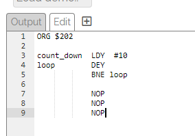
count_down      LDY     #10         ; Set Y to 10

loop            DEY                 ; Subtract 1 from Y, setting the zero flag if we've reached zero
                BNE     loop        ; If the zero flag isn't set, do it again
You can try this program in the Cerberus emulator. Remember to
add a line at the start ORG $202 to set the start address of the program so it is ready to run, and add some ‘NOP’ instructions after the program so there is something for the
CPU to do when it has finished counting. Your program should look like this:
Click Assemble, then click Step a few times to see how the program runs. Look at the Y register and the Flags register on the left of the screen to see how they change.
You can click Reset to
run the program from the start.
Memory Addressing
The 6502 processor family has a major restriction in the way it can access memory, only having one register (the program counter) that can address the full 16-bit (64K) range of memory. As the program counter is completely tied up reading the instructions to be executed, the processor has to use a variety of addressing modes to provide flexible ways to read and write memory locations.
Our terrible piece of code used the simplest form of addressing the 6502 supports, direct addressing, where the address we want to write or read from is hard coded into the
instruction itself. There are actually two forms of direct addressing, absolute and zero page. Absolute addressing builds a full 16-bit address value into the instruction and can
therefore read or write to any location in memory. The ‘cost’ is that the instruction takes up more memory (three bytes, one for the instruction and two for the address), and
is slower to execute (as the processor has to read the full address). Zero page addressing saves some of this cost by using only one byte for the address, but can therefore only address
the first 256 memory locations, known as the ‘zero page’.
In fact, the zero page is used heavily by the 6502, both to extend it’s very limited number of registers and to add a variety of more exotic addressing modes. Individual bytes in zero page can be used to efficiently store and retrieve values being used for calculations. However, they can also be used in pairs to provide a 16-bit value that we can use as an address. This is called indirect addressing where we read a value from memory and then use that value as a pointer to the memory location we want to access.
Let’s look at an example.
Remember that the memory location of the first character on screen is $F800. We can store this 16-bit value as two bytes in zero page. The 6502 is little endian, which means
that when we’re dealing with values that take up more than a single byte (8 bits), we store the least significant byte first, and then the next most significant byte and so on.
For our 16-bit value of $F800, we therefore store $00 (the least significant, or low byte) in the first memory location, and $F8 (the most significant, or high byte)
in the second memory location. We can chose any memory location in zero page to store our 16 bit value, but for now let’s pick address $30 (and therefore also $31) to store our two bytes.
The code to write our 16-bit value looks like this:
            LDA    #0    ; Load the low byte
            STA    $30   ; Store it at address $30
            LDA    #$F8  ; Load the high byte
            STA    $31   ; Store it at address $31
Notice that we have loaded the accumulator with two immediate values, and stored those values in two absolute, zero page memory locations. Now, let’s use that 16-bit value to write to the screen.
            LDA    #66   ; Load A with the value of character 'B'
            STA    ($30)
The key instruction here is STA ($30). This is our first example of indirect addressing. Previously when we put a number after a Store instruction it was the address we want to
write to (direct addressing). However, in this case, we have round brackets around the number, which indicates that we want to read the two bytes starting at that address and then
use that value as our address to write to. Since we stored the 16 bit value $F800 at address $30 in our previous bit of code, the processor will Store the value in register A at
address $F800. This instruction therefore writes the character ‘B’ to the first cell in the screen map. Round brackets show that we are using indirect addressing, and not storing
anything at address $30.
We can even increment our 16-bit value and use it to write the same character to the next screen location:
            INC   $30    ; Increment the value at address $30
            STA   ($30)
Now, if we look up the INC instruction in the reference guide, we will discover something interesting. It sets the zero flag when the byte it is incrementing wraps
round to zero (remember a byte holds an 8-bit value from 0 to 255. When we add one to 255, it simply wraps round to 0 again). We can use this fact to spot when the least
significant (low) byte of our 16-bit value has been incremented 256 times. Our full program looks like this:
ORG $202

            LDA    #0       ; Load the low byte
            STA    $30      ; Store it at address $30
            LDA    #$F8     ; Load the high byte
            STA    $31      ; Store it at address $31

            LDA    #66      ; Load A with the value of character 'B'
loop        STA    ($30)
            INC    $30      ; Increment the least significant (low) byte of our indirect address
            BNE    loop     ; And loop if it hasn't wrapped round to zero

forever     BRA    forever  ; Wait forever
Take a look at the program and see if you can work out what it will do. Then try it out in the emulator.
Were you right?
What you should see when you Assemble and then Run this program, is that it writes the character ‘B’ to the first 256 screen locations. We’ve stored a 16-bit address in zero page. Then
we’ve used indirect addressing to write values to that 16-bit address. We’ve incremented the low byte of our 16-bit address, and so long as it hasn’t wrapped around, we’ve
kept on writing values. The three lines of code starting at the loop label replace 256 lines of our terrible first attempt!
We now have nearly enough to be able to complete our routine - all we have to do is write the remaining 944 characters ( = 1200-256).
Completing the Routine
So far we’ve incremented the low byte of our address pointer until it wraps around. To write to the next 256 screen locations, we then have to increment the high byte by one.
Our routine above counts from $F800 to $F8FF and then wraps to $F800 again - we need to step it on to $F900 instead. We do that by incrementing the second
byte of our indirect address, with an INC $31 instruction. We can then write another 256 bytes, before having to increment it again (to $FA00), and so on until we’ve written
the full extent of the screen map. We are writing to pages $F8, $F9 and so on.
Our lives are made slightly more difficult by the fact that the 1200 characters of the screen map aren’t an exact multiple of 256. We actually want to stop at address $FCAF - no
convenient ..00 in the low byte.
We can easily detect when the INC or DEC (decrement) instructions wrap around to zero every 256 steps, but detecting a value in the middle needs an extra instruction
(which we’ll explore in a moment). However, we can save that extra instruction with a simple trick.
If we notice that the screen map addresses start on an exact 256 byte (page) boundary (the least significant byte of $F800 is $00), rather than counting up to the middle of a page
we can instead count down to an easily detected zero. We already have to detect that zero event in order to update our high byte at the end of each page, so we get two checks for the
price of one.
In pseudocode our routine now looks like this:
clear_screen        Set a pointer to just after the last character on screen, $FCB0

loop                Decrement (subtract one from) low byte of the pointer

                    Write a blank character to the pointer location

                    If the low byte hasn't reached zero repeat the loop

                    Otherwise subtract one from the high byte of the pointer

                    Check to see if we're now before the first page of the screen map

                    If we're not, repeat the loop

                    Otherwise, we're done!
The order of instructions here might seem a little odd, but it makes testing if the low byte will wrap around easier. It relies on the fact that the DEC (decrement) instruction
sets the zero flag when it’s target reaches zero, but the STA (store) instruction does not change any flags, so we can decrement, write and then test to see if the decrement
instruction reached zero.
Finally, we need to check if we’re before the first page of the screen map. This is when the high byte of our pointer is less than $F8. How do we test for
an exact value? This is where the compare instruction comes in. The compare instruction compares a register in the 6502 to a memory location, and sets the zero flag if they
are the same. The BNE instruction then means “branch if the register and memory location are not equal”. So we can store the value we want to detect ($F7) in the X register,
compare it to our pointer with the CPX instruction and branch if they’re not equal.
Here’s our final routine:
ORG $202
                            ; Set our pointer to $FCB0:

            LDA    #$B0     ; Load the low byte
            STA    $30      ; Store it at address $30
            LDA    #$FC     ; Load the high byte
            STA    $31      ; Store it at address $31

            LDA    #32      ; Load A with the value of the space character
            LDX    #$F7     ; Load X with the page number to end on, $F7

loop        DEC    $30      ; Decrement the low byte of our pointer
            STA    ($30)    ; Write out our character
            BNE    loop     ; And loop if the low byte of the pointer hasn't reached zero

            DEC    $31      ; We've wrapped around, so decrement the high byte
            CPX    $31      ; Is the high byte $F7?
            BNE    loop     ; Loop if it isn't

forever     BRA    forever  ; Wait forever
Try this in the emulator and see if it behaves as you expect. If you’ve already assembled and run a program, you might need to STOP the emulator and REBOOT it to clear out any
previous code. Note that you can change the value in the LDA #32 instruction to fill the screen with any character you like.
Well Done!
This is a huge step to have a working program that does a useful task for us. Well done if you got this far. We’ve introduced a lot of new concepts in this post, which may seem overwhelming, but gives us a great foundation to start building our game.
In the next post, we’ll tidy our code up a little and continue with the job of drawing a game level to the screen.